Let's play with sensors.
Part of this assignment is also covered on my final project's page.
This article is part of: fabacademy2020.
Let's play with sensors.
Part of this assignment is also covered on my final project's page.
The ultrasonic sensor HC-SR04 provides 2Cm to 400cm of non-contact measurement functionality with a ranging accuracy that can reach up to 3mm. Here is its datasheet. This sensor has 4 pins that we have to connect to our dev board.
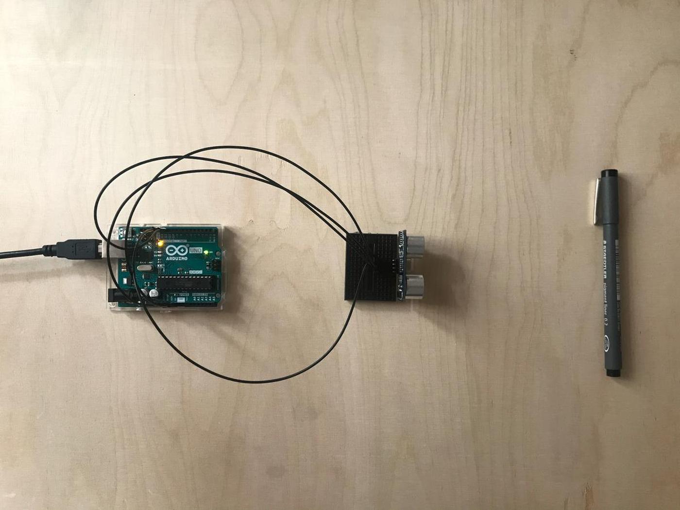
I'm using an Arduino UNO to use this sensor because it needs a voltage of 5V. Unfortunately, the Barduino and its ESP32 only has a voltage of 3.3V.
The connection is quite simple, the VCC goes to the 5V, the GND to the GND, the Echo to a digital pin, let's say the 12 and the Trig to another digital pin, the 11.

Here is the basic code to read data from the ultrasonic sensor, to convert them into readable values (cm) and print it on the serial monitor.
To quickly create a PlatformIO project for the Arduino UNO, open a terminal and navigate to a freshly created folder and type $ pio project init --board uno. As simple as that.
Create in new main.cpp file into the src folder.
int trigPin = 11;
int echoPin = 12;
long duration, cm;

void setup() {
  Serial.begin(9600);
  pinMode(trigPin, OUTPUT);
  pinMode(echoPin, INPUT);
}

void loop() {
  digitalWrite(trigPin, LOW);
  delayMicroseconds(5);
  digitalWrite(trigPin, HIGH);
  delayMicroseconds(10);
  digitalWrite(trigPin, LOW);
  pinMode(echoPin, INPUT);
  duration = pulseIn(echoPin, HIGH);
  cm = (duration/2) / 29.1;
  Serial.print(cm);
  Serial.print("cm");
  delay(250);
}
Compile it and upload it to the UNO pio run -t upload and open the serial monitor pio device monitor to see the distance value calculated by the ultrasonic sensor. I'm impressed how fast and accurate it is.
cm = (duration/2) / 29.1 is how we convert the duration to a distance, using a formula: distance = (traveltime/2) * speed of sound. The speed of sound is 343m/s wich is equal to 1/29.1 cm/uS. We need to divide the traveltime by 2 because the wave we sent hit the object and then returned back to the sensor.
Or how to measure temperature using a resistor.
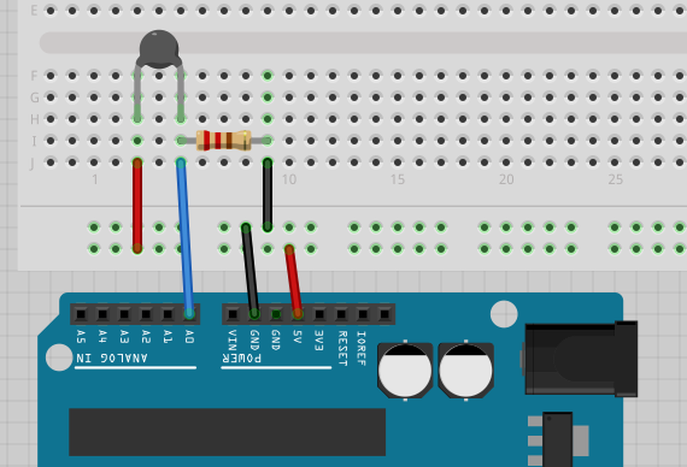
To measure the temperature, we need to measure the resistance. However, a microcontroller does not have a resistance-meter built in. Instead, it only has a voltage reader known as a analog-digital-converter. So what we have to do is convert the resistance into a voltage, and we will do that by adding another resistor and connecting them in series. Now you just measure the voltage in the middle, as the resistance changes, the voltage changes too, according to the simple voltage-divider equation. We just need to keep one resistor fixed
Analog Voltage Reading Method, Adafruit

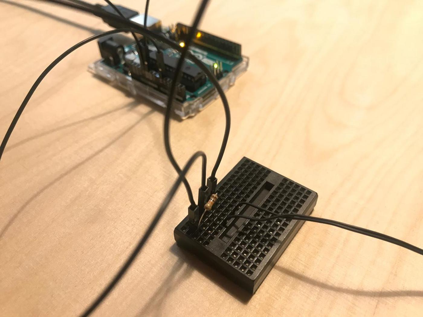
The thermistor is linked to the GND, and to the analog pin 0 and to the 5V pin through a 10 resistor.
Here is the piece of code that print the value of the analog pin 0 and convert its values into a Celcius temperature value.
#include <Arduino.h>
#include <math.h>

void setup()
{
  Serial.begin(9600);
}

// Function that applies the Steinhart-Hart equation
float thermistor(int val)
{
  float temp;
  // From raw analog values
  temp = log(((10240000 / val) - 10000));
  // To Kelvin values
  temp = 1 / (0.001129148 + (0.000234125 + (0.0000000876741 * temp * temp)) * temp);
  // Convert Kelvin to Celsius
  temp = temp - 273.15;
  return temp;
}

void loop()
{
  int val;
  float temp;
  val = analogRead(0);
  temp = thermistor(val);
  Serial.print(temp);
  Serial.println(" °C");
  delay(1000);
}
Main resource: this tutorial
Water is a conductive element, and the more water there is in the soil the more electricity can flow through it. So, in order to measure the soil moisture level, we can integrate it into an electrical circuit and measure the voltage. The more voltage in the circuit, the more water there is in the soil.
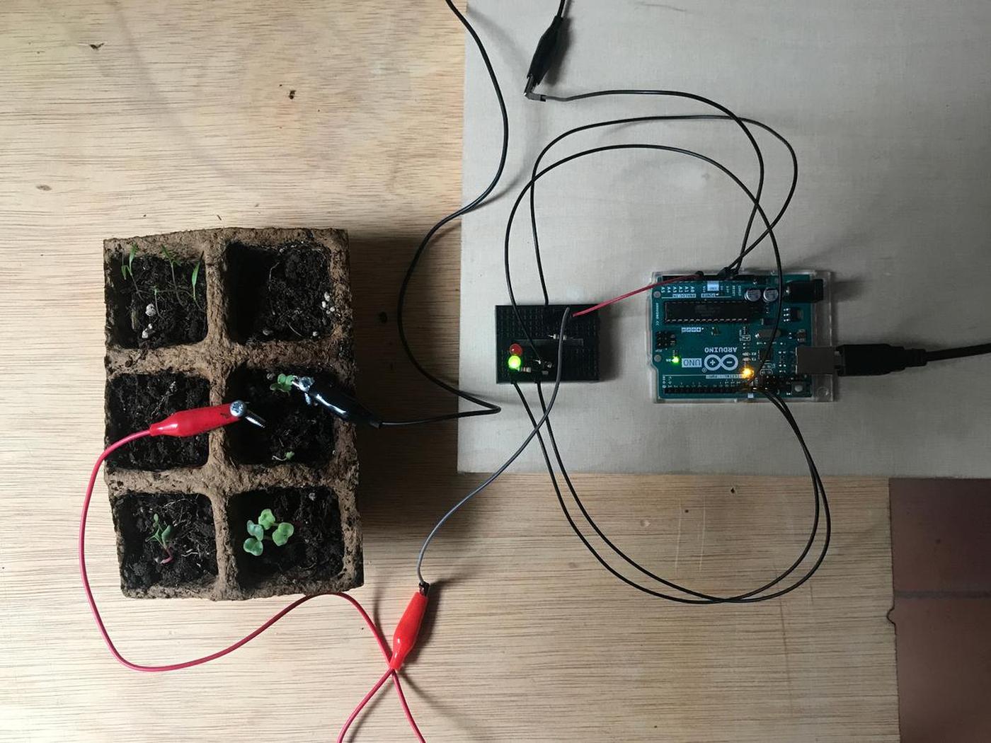
To represent it, I built a small system that lights a green LED when the soil is wet and a red LED when it's dry.
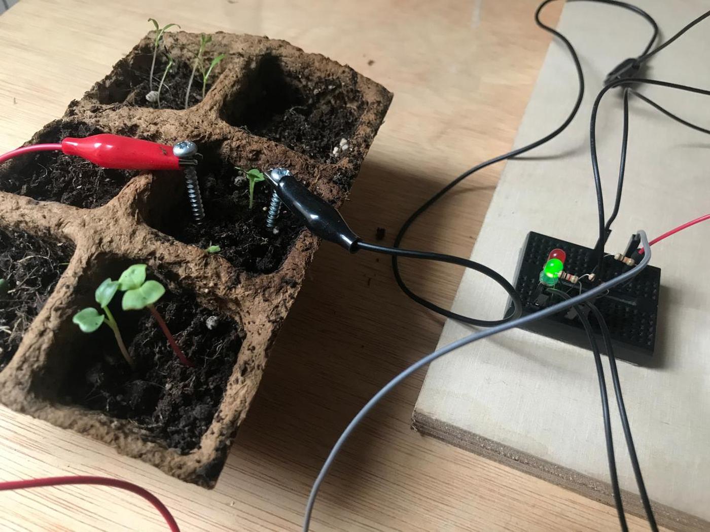
The code is basic. If the analog pin gets a high voltage, it means that the soil is moist and the plant is happy so we turn on the green LED, and vice versa.
I plan to write a more complex code in the coming weeks, a code that takes into account the amount of water needed for each specific plant, and to alert when it's too dry or too weet.
int ledGreen = 12;
int ledRed = 11;
int contactVal = 0;

void setup() {
  Serial.begin(9600);
  pinMode(ledGreen, OUTPUT);
  pinMode(ledRed, OUTPUT);
}

void loop() {
  contactVal = analogRead(0);
  Serial.println(contactVal);
  if (contactVal >= 350) {
    digitalWrite(ledRed, LOW);
    digitalWrite(ledGreen, HIGH);
  } else {
    digitalWrite(ledRed, HIGH);
    digitalWrite(ledGreen, LOW);
  }
  delay(250);
}
Here is my tiny system in action, olé.
In the frame of my Fab Academy final project, I'm exploring how to sense the electrical activity of plants.
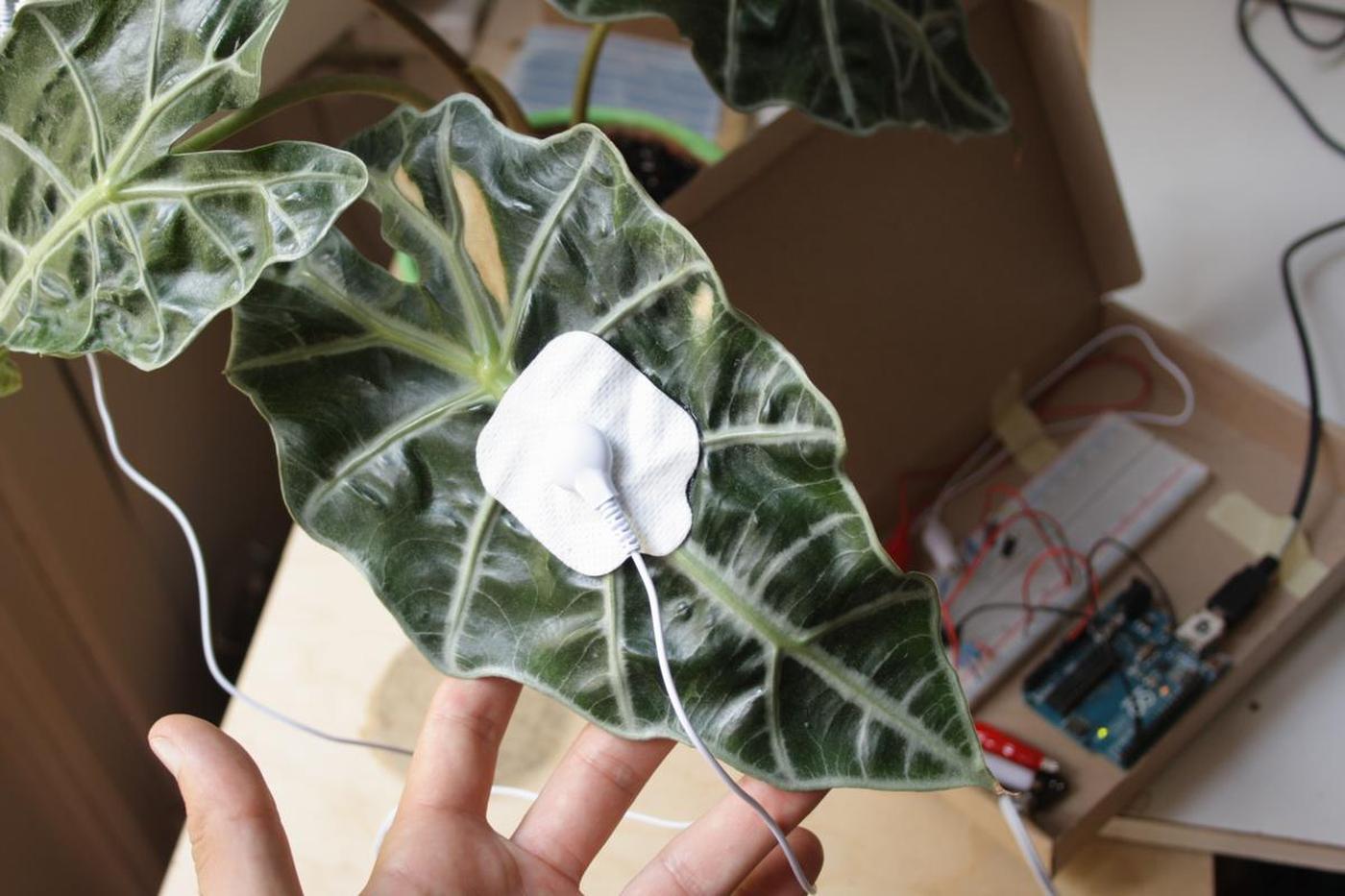
I covered this topic on a different article.